Electric Imp
Today I came across a news article on Engadget about a new development that promises to allow you to connect almost anything that uses electronics to the internet and to each other.
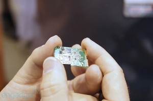
It’s called the Electric IMP and it’s essentially an ARM Cortex M3 and WiFi built into an SD card space envelope, it looks exactly like and SD card, it even has the same contacts.
To set up the WiFi connection there’s an app for both the Iphone and Android devices which takes the setup information for your Wifi and then transmits them to the Imp by flashing the screen on and off, the Imp reads this data through the front of the card and sets up the WiFi.
Once connected the code, written in Squirrel, is edited in your browser, on their server (I think) and downloaded into the Imp via the WiFi connection.
The other interesting aspect is that they provide a service on their servers which allows you to connect your Imps together visually, using blocks, and writing code to interconnect them across the Internet so they can talk to each other.
You can also create virtual Imps that are used to connect to Internet services outside the Imp servers, I assume that you could set up a virtual Imp to wait for a tweet from you to switch on the lounge light and that would then be sent to you real Imp, at home, which would then switch on the light or even monitor the temperature at home with an Imp and get a virtual Imp to send you a SMS message when it reaches a certain temperature.
The possibilities seem endless. They are showing some development hardware to go with the Imps the most interesting (for me) is the Imp enabled Arduino, the Duino.
The Dunio seems to be a full standalone Arduino clone with a twist, the twist being an Imp slot instead of the normal USB connector, this means that you write the Arduino code in the Arduin IDE (modified?) and then send the code to the Duino via the WiFi so your Duino can be anywhere in the world, with a WiFi connection.
Another board from Arduino.cc
Another board from Arduino.cc
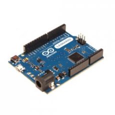
Arduino have announced another micro-controller board based on a new ATmega32u4, this processor also takes care of the serial communications with the host PC negating the need for a separate serial to USB chip.
- A micro USB connector. At last!
- The SPI bus on the ISP connector no-longer uses any IO pins.
- The device will act as a USB keyboard or mouse to the host PC.
- The board is available with or without the headers, without being slightly cheaper.
Using Notepad++ as the editor for Arduino Sketches
I’ve started using Notepad++ again after a long break from programming my Arduinos and Jeenodes and found that you can use NPP to edit the .ino files and then use the NPPexec script to run the Arduino IDE and load the sketch, then you can just compile and upload.
To set this up follow the video below: –
Once you have the script
D:\My Documents\Downloads\arduino-1.0\arduino.exe “$(FULL_CURRENT_PATH)”
You can add it as a macro by pressing F6 and pasting it into the execute dialog and saving it.
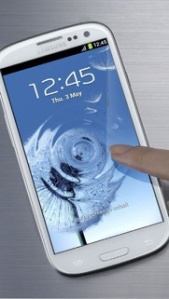
The new Galaxy S3
The Arduino and Pachube
I’ve not played with the Arduino for some time but this weekend I dusted it off and decided to have go at getting it logging some data and uploading it to Pachube.
This was due mainly to a conversation at work, extolling the virtues of the Arduino and how simple it was to connect to the internet.
So after getting the hardware out of the box and overcoming all the library related issues with using the newer Arduino 1.00 instead of 022 I started to look for some code to use as the basis of my little project.
Firstly I found the Pachube example from the Arduino website here, this sketch gives you all the basics to upload a data stream to Pachube.
The code has sections at the top to setup your access information to Pachube so first you need to get an account with Pachube, it’s free for a basic account.
#define APIKEY “YOUR API KEY GOES HERE” // replace your pachube api key here#define FEEDID 00000 // replace your feed ID
#define USERAGENT
- Visit www.pachube.com and signup for an account.
- Log into Pachube and setup a feed.
- Add a datastream, this will be you sensor data, type in “sensor1” to match the example sketch and save.
- Create a key for your feed using “My keys” on the right.
Now you can replace the APIKEY text in the sketch with the key you’ve generated on the Pachube site, FEEDID with the number you find on your edit feed page, near the bottom, just use the number after the /feeds/.
I used my feed title to replace USERAGENT.
I then loaded the sketch into the Arduino and off she went.
Log into your Pachube account to see if the data is updating. There is some useful help if it doesn’t seem to work, on the right select the “Debug info” item and this takes you to a log of the data that Pachube is receiving.
You can see from the request body that I have some extra data added that’s not part of the example sketch, this is temperature data from a DS18B20 temp sensor, I’ll show the extra code to get this done in my next Blog post.
There are also lots of ways to view the data on the web: –
- On the Pachube website.
- Adding a graph to your own blog, see top right.
- Using the embedded graph code on your own website.
- Using a gadget on you iGoogle home page.
- Using an App on you Apple Ipod touch or Iphone.
- Using an App on you Android Phone.
First project with the Jeenode and GLCD
Having had my Jeenodes for a while now and eventually got some code to actually work, reading DS18B20s and displaying the results on a 16×2 line display, I fancied getting to grips with the GLCD, also from Jeelabs.
This is just a project to help me learn about the hardware and software, it may be useful in to someone out there. I’ve tried to put plenty of comments in the code, mainly so I remember what I did when I look at it in two weeks time.
My target project is to create a portable (small) display that I can control the central heating from, i.e. room temp., heating on/off and hot water temp. control. This project is the prototype phase.
At first it was a bit of a slog trying to understand the glcd library and how to send float variables to the screen (C++ is a new language for me), after that came the RTC coding to get the time on the screen, especially with leading zeros.
What I eventually came up with was a display showing the time, with leading zeros (thanks to ‘sprintf’), two temperature inputs and a trend line showing just over two hours history for the current temperature.
The temperatures are derived from two DS18B20s connected to port2, adding extra sensors should be easy enough. Each sensor has a Max. and a Min. point displayed.
The trend line is generated by sampling the temp. every minute, based on the now.minute() value from the RTC and then plotted between rows 40 to 60 using the glcd.setpixel command and the map function to map from 10 to 30 degrees C. This time could be altered to be shorter or longer, as desired.
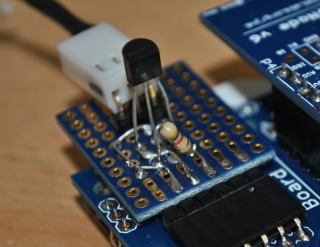
The hardware is basically a Jeenode V6, GLCD PCB and display, RTC plug (Port 3) and a DS18B20 soldered to a small prototyping board plugged into port 2.
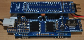 |
| DS18B20 on the Left and the RTC plug on the Right |
On the DS81B20 PCB there is also a three pin right angle connector for the exernal DS18B20 probe, bought from Ebay.
The sofware is based on the Jeelabs demo sketches from Jeelabs rtcplug and the GLCD demo sketches.
The temperatures are also sent out over the serial link to the PC, formatted as they are seen on the GLCD.
There are still some issues and some improvements to be made:-
- The DS18B20 disconnected detection doesn’t seem to work.
- If the DS18B20 is disconnected and then, when reconnected, the Max temp. reads 85 Deg.
Future improvements
- To set the time I used another sketch but I plan to add the ability to set the time using my VB software from the PC.
- Automatically alter the trend line scale based on the readings.
- Round up the temp. for the pixel to the nearest degree.
- Make the trend line update in seconds and put it in a variable.
Next steps
- Learn how to send/receive remote data from other Jeenode/Uno
- Find out if I can use different size fonts on the GLCD (not the really big ones)
Code: –
/* Based on Demo display for the Graphics Board and the rtcplug.pde from Jeelabs
 2010-11-14 <jcw@equi4.com> http://opensource.org/licenses/mit-license.php

 Added DS18B20 sensors and RTC plug
 Displays time, internal and external temp with min and max readings there is also a trend
 line drawn at the bottom of the LCD.  It samples the current temp. every minute, using RTC,
 and draws a pixel at a point between row 40 to 60, using the map command for temp's between
 10 and 30 degrees.  It takes 126 min's to draw the line then it clears the line and
 starts again.
*/
#include <GLCD_ST7565.h>
#include <Ports.h>
#include <RF12.h> // needed to avoid a linker error :(
#include <avr/pgmspace.h>
#include <OneWire.h>
#include "Wire.h"
#include <RTClib.h>
#include <DallasTemperature.h> //Version 3.6
#define ONE_WIRE_BUS 5  // DS18S20 Temperature chip i/o on pin 5 - Port 2

GLCD_ST7565 glcd;

EMPTY_INTERRUPT(WDT_vect);

OneWire oneWire(ONE_WIRE_BUS);// Setup a oneWire instance to communicate with any OneWire devices
DallasTemperature sensors(&oneWire);// Pass our oneWire reference to Dallas Temperature.
// Global variables
char outBuf [25];
int MaxTempIn=0; //hold max temp value
int MinTempIn=500; //hold min temp value, pre load with 500 because the first test is against the temp val * 10
int MaxTempOut=0; //hold max temp value
int MinTempOut=500; //hold min temp value, pre load with 500 because the first test is against the temp val * 10
int LastMin; //Hold last min value
int x=0; //counter for trend line first pixel will be 0 plus 1 as the border is 0.
int Ypixel; // Y value for trend line
// Insert the ID of your temp sensor here, for the sketch, visit here
// http://www.hacktronics.com/Tutorials/arduino-1-wire-address-finder.html
DeviceAddress insideThermometer = { 0x28, 0x2F, 0x8A, 0xEE, 0x02, 0x00, 0x00, 0xE9 }; // none probe
DeviceAddress outsideThermometer = { 0x28, 0x60, 0x3A, 0x10, 0x03, 0x00, 0x00, 0x38 };
DeviceAddress WaterThermometer = { 0x28, 0xB3, 0x58, 0x18, 0x03, 0x00, 0x00, 0x2B };
class Sleepy;

// RTC based on the DS1307 chip connected via the Ports library
class RTC_Plug : public DeviceI2C {
    // shorthand
    static uint8_t bcd2bin (uint8_t val) { return RTC_DS1307::bcd2bin(val); }
    static uint8_t bin2bcd (uint8_t val) { return RTC_DS1307::bin2bcd(val); }
public:
    RTC_Plug (const PortI2C& port) : DeviceI2C (port, 0x68) {}

    void begin() {}

    void adjust(const DateTime& dt) {
        send();
        write(0);
        write(bin2bcd(dt.second()));
        write(bin2bcd(dt.minute()));
        write(bin2bcd(dt.hour()));
        write(bin2bcd(0));
        write(bin2bcd(dt.day()));
        write(bin2bcd(dt.month()));
        write(bin2bcd(dt.year() - 2000));
        write(0);
        stop();
    }

    DateTime now() {
      	send();
      	write(0);
        stop();

        receive();
        uint8_t ss = bcd2bin(read(0));
        uint8_t mm = bcd2bin(read(0));
        uint8_t hh = bcd2bin(read(0));
        read(0);
        uint8_t d = bcd2bin(read(0));
        uint8_t m = bcd2bin(read(0));
        uint16_t y = bcd2bin(read(1)) + 2000;

        return DateTime (y, m, d, hh, mm, ss);
    }
};

PortI2C i2cBus (3); //RTC on port 3
RTC_Plug RTC (i2cBus);

void setup () {
DateTime now = RTC.now();
LastMin = now.minute(); //Store minute value for use in Draw Graph

// Set serial speed
  Serial.begin(57600);
  // Start RTC
	RTC.begin();
// Power down the Transceiver
    rf12_initialize(1, RF12_868MHZ);
    rf12_sleep(0);
// Start the temp sensors
    sensors.begin();

// set the resolution to 12 bit
    sensors.setResolution(outsideThermometer, 12);
    sensors.setResolution(insideThermometer, 12);
	//sensors.setResolution(WaterThermometer, 12);
    Wire.begin();

 // Initialise the GLCD
    glcd.begin();
    glcd.backLight(255);
    glcd.drawString_P(0,  10, PSTR(" Now Max Min")); //Set the column titles
    //glcd.drawLine(0, 8, 120, 8, WHITE);
    glcd.drawRect(0, 8, 128, 56, WHITE);
    glcd.refresh(); // Update the display
}

void loop () {
	DateTime now = RTC.now();
  sensors.requestTemperatures();// Trigger all the temp sensors to carry out a temp. conversion
  Sleepy::loseSomeTime(2000); // Do nothing for n seconds, slow update OK

  printTemperature(insideThermometer); // Read in the temp. data from the inside sensor
  printTemperature(outsideThermometer); // Read in the temp. data from the outside sensor
  UpdateTime();
  //Trigger a pixel to be drawn on the history every minute
  if(now.minute() > LastMin) {
    DrwGraph();
    LastMin = now.minute();
  }
  if(LastMin > now.minute()) {
  LastMin=1; //reset to 1 as rollover to next hour.
  }
  glcd.refresh();
 }

void UpdateTime(){
	DateTime now = RTC.now();
	sprintf(outBuf, "Time %02d:%02d",now.hour(), now.minute()); //Format the time without seconds
	glcd.drawString(3, 0, outBuf); //Print to Screen RAM
	Serial.print(now.hour(), DEC);
    Serial.print(':');
    Serial.print(now.minute(), DEC);
    Serial.print(':');
    Serial.print(now.second(), DEC);
    Serial.print(" - ");
    Serial.print(now.day(), DEC);
    Serial.print('/');
    Serial.print(now.month(), DEC);
    Serial.print('/');
    Serial.print(now.year(), DEC);
    Serial.print("\n");
  }

void printTemperature(DeviceAddress deviceAddress) {
int temp2; // Create variable to hold the int value of the float without the decimal
float tempC = sensors.getTempC(deviceAddress); // read the specific sensor called from loop.

if (deviceAddress == insideThermometer){ //Display Internal Temp

if (tempC == -127) {
      glcd.drawString(10,  20, PSTR("Error"));
} else {
  temp2 =tempC *10 + 0.5; // make now temp decimal value into an integer. remove decimal point
   Ypixel = temp2/10; // Store Y pixel value temp for trend line
  // Ypixel = temp2%10; // Option store Y pixel value temp decimal for trend line
  if (MaxTempIn < temp2){ //Set MaxTempIn to temp2 if higher than old MaxtempIn
    MaxTempIn=temp2;
}
if (MinTempIn > temp2) { //Set MinTempIn to temp2 if Lower than old MinTempIn
	MinTempIn = temp2;
}
  // Print Inside Temps, Now, Max and Min.
  //Format the integer back into integer and decimal
  sprintf(outBuf, "In %d.%d %d.%d %d.%d",temp2/10, temp2%10,MaxTempIn/10, MaxTempIn%10,MinTempIn/10, MinTempIn%10);
  glcd.drawString(3, 20, outBuf); //Print to Screen RAM
  Serial.print(" Now Max Min");
  Serial.print("\n");
  Serial.print(outBuf); //send data to host
  Serial.print("\n");
}
}
if (deviceAddress == outsideThermometer){ //Display Outside Temp
if (tempC == -127) {
      glcd.drawString(10,  30, PSTR("Error"));
} else {
  temp2 =tempC *10 + 0.5; // make now temp decimal value into an integer. remove decimal point
  if (MaxTempOut < temp2){ //Set Max temp2 if higher than old Maxtemp
    MaxTempOut=temp2;
}
if (MinTempOut > temp2) { //Set Min temp2 if Lower than old Mintemp
	MinTempOut = temp2;
}
// Print Outside Temps, Now, Max and Min.
//Format the integer back into integer and decimal
  sprintf(outBuf, "Out %d.%d %d.%d %d.%d",temp2/10, temp2%10,MaxTempOut/10, MaxTempOut%10,MinTempOut/10, MinTempOut%10);
  glcd.drawString(3, 30, outBuf); //Print to Screen RAM
  Serial.print(outBuf); //send data to host
  Serial.print("\n");
}
}
}
void DrwGraph(){ //Plot next pixel of temp history

if (x < 126){ //Check if the end of the visible screen is reached
x++; //Increment x for next pixel
// draw pixel, Y value mapped from temp value to Y pixel range, reversed.
// glcd.setPixel(x,map(Ypixel,10,30,60,40),WHITE);
glcd.setPixel(x,map(Ypixel,0,9,60,40),WHITE);
//glcd.drawLine(x-1,map(OldPixel,0,9,60,40),x,map(Ypixel,0,9,60,40),WHITE);
//int OldPixel = Ypixel; //store last value
}
else{
glcd.fillRect(1,40,126,20, BLACK); //Draw rectangle in Black to erase previous line
x=1; // Start at left hand of visible screen again.
}
}
Next consumer computing phase ?
Every now and then something comes along that changes people’s attitudes towards technology, for me there was the VHS/Betamax video recorder, the Commodore VIC20, the BBC Micro, the CD player, to name a few.
For me, the main impacts have always been with the introduction of new computing technologies, like the first Toshiba dual floppy DOS based laptop I had access to at work, closely followed by my own 286 Turbo PC I built at home.
The last key step in computers, for me, was the Netbook, inspired by the goal to supply cheap computing to the third world it soon became a whole new platform that was so much more portable.
Of course there is tablet computing but as yet I’ve not found the need to spend the money to go there!
Now there is a branch of computing technology to embrace and it looks like it will be very affordable, the Raspberry Pi.
Being developed by the Raspberry Pi Foundation, a UK registered charity, they hope it will become an ultracheap computer platform to be used to teach children about computing. It may even be cheap enough for them to be given to school children, around £15.
The ultra small device features a HDMI port at one end and a USB port on the other.
It is shown on the foundations website running Ubuntu whilst connected to a USB hub, USB to network adapter and a PC monitor.
They hope to have something out within 12 months; I’ll definitely be getting one.
There is a Youtube video here.
Free Web based Auto-routing Software
Whilst on my internet travels I came across a really useful site for autorouting PCBs, the application is Java based and runs from the website.
It’s compatible with most main PCB design SW like the free version of CADsoft-Eagle and even though it’s still in the development phase, its on-line version is free to use.
So if you’ve got a nice Arduino clone design and you want to optimise the PCB by reducing the amount of vias you have then give it a try, if you haven’t got a PCB ready then you can still give it a try with the demo files supplied.
The site can be found here http://www.freerouting.net/
>Jeenodes are here
>At last my Jeenodes arrived and I started to programme them with some of the code I was using on the Arduino UNO to display temperatures from a DS18B20 on the LCD.
I was now using the I2C LCD interface from Jeelabs (LCD Plug) so I used the Demo LCD sketch from Jeelabs and modified it using the Dallas temperature library to read a DS18B20 conected to port 4.
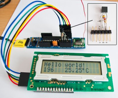 |
| Jeenode V6 with DS18B20 and I2C LCD |
I have the Graphic board on order so I can use a large display and, using the code from Jeelabs, create a remote temp. sensing and control unit for my central heating control project.
The built in 868MHz Transciever will allow comm’.s back to the control unit in the airing cupboard.
Hopefully with the efforts made by Jeelabs to extend battery life I hope to get months of usage from a couple of AA batteries.
>Using Notepad++ with Arduino sketches
>After using both the Arduino IDE and VB express I’m always a little disappointed at the lack of helper features in the Arduino IDE, of course it is a little unfair to compare the two when you consider the differences in available resource! the Arduino IDE is still pretty good.
 |
| Functions contracted |
I have used Notepad++ for some time as a general text editor on my PC and I thought I’d give it a try as an editor for my pde files.
